
Technical File of the EWD-H-J3 Intelligent Elevator Load Weighing Device [User’s Guide] [V2.2]
USER’S GUIDE
EWD-H-J3
(V2.2
)
Xi'an Excellent Electromechanical Co.,Ltd.

Technical File of the EWD-H-J3 Intelligent Elevator Load Weighing Device [User’s Guide] [V2.2]
Page1 of 15
Table of Contents
Product Overview
1、Product Appearance, inner structure and interface directions
…………………
Page 2
2
、
Exterior dimensions and installing diagram
…………………
Page 3
Installation & Adjustment
3
、
System Adjustment and directions
…………………
Page 4
Implication and
Adjustment Method of the
Operation Parameters
4、System Parameters Adjustment
…………………
Page 6
5
、
Explanation of the Meaning of Parameter P
…………………
Page 7
Indicating Code
Explanation
6、Explanation of System Normal Operation Code
…………………
Page 9
7、Explanation of other displaying
…………………
Page 9
How To Do?
8、Brief introductions of conditions
…………………
Page 10
9、How to do setting adjustment of an elevator with the known “no
load rated load”compressing deformation?
…………………
Page 10
10
、
How to repeat the Autotune operation for the system
?
…………………
Page 11
11
、
How to modify the system output conditions after Autotune
?
…………………
Page 11
12、How to use 20% rated load autotune?
…………………
Page 11
13、Car shock rubber compression exceeds the sensor detection range
…………………
Page 11
14、On the use of "load increase, away from" working methods of operation
…………………
Page 11
System Characteristics
15
、
Working principle of
“
EWD-H-J3
”
elevator weighing device
…………………
Page 11
16、Main Properties
…………………
Page 12
17、Technical Items
…………………
Page 12
Promise
…………………
Page 13
Others
…………………
Page 14
Caution: This system is applicable an elevator with「moveable car platform」.Before use, please read the following content carefully.
The Inductive magnet is specially-made rare-earth magnet for this product with strong magnetic force. Special care should
be taken during installation. Under no condition should it be away from the high temperature above 100℃ to avoid
demagnetizing and the equipment damage and personal hurt from this is beyond our responsibility.
Notice
:
Our part is just responsible for the products quality in the guarantee period under any condition.
Declaration:Our company reserves the right of changing products for technical improvement and the related technical parameters
should be referred to the USER’S GUIDE along with the products.
Technical File of the EWD-H-J3 Intelligent Elevator Load Weighing Device [User’s Guide]
Page2of15
Product Overview
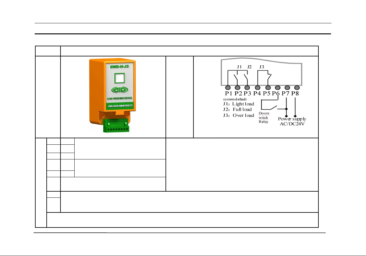
1、 Product Appearance, Interior Structure and Interface Directions:
EWD-H-J3
Appearance
Interior
Tructure
Interface Directions
P1
Com
Common terminal“Com”: 2-channel
solid-state relay output
P2
J1
P3
J2
P4
J3.1
Independent 1-channel solid-state
relay output
P5
J3.2
P6
Cooperate with P7 to hold J1 ~ 3 status
(Unused normally)
P7
①
System Power Source
:
DC/AC24V(
±
10%)
/
150mA
②
Absolutely not to connect the output terminals of this device except
“
P7
、
P8
”
to exterior power source
directly, and the permanent damage from this is beyond our responsibility.
P8
1.J1
~
J3 are interior solid state relays with Max. loading capacity of DC/AC 32V/50mA
。
2.To be programmed as
“
no load
~
over load
”
output signal to participate in elevator logic control.
Technical File of the EWD-H-J3 Intelligent Elevator Load Weighing Device [User’s Guide] [V2.2]
Page3 of 15
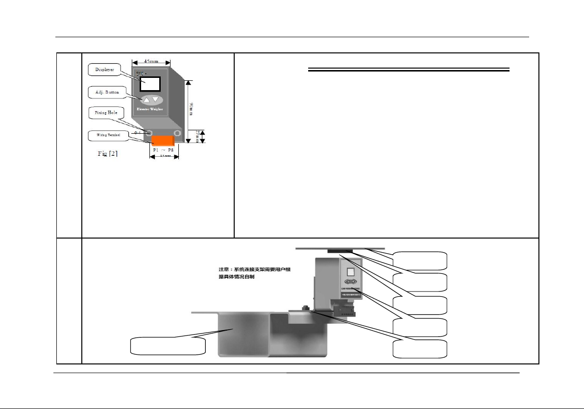
2、Exterior Dimensions & Installing Scheme
E
xterior Dimension
Notice on Installation
1.Install this device as near as possible to the center of elevator car
platform or the original place of elevator overload switch. The
system should be installed on the bottom bearing beam of
elevator car platform with the inductive magnet adhering to the
moveable car platform and the marking surface facing to the
inductive point of the weighing device.
2.The system supporting frame should be made according to
elevator concrete situation with the uneasily deforming material of
thickness more than 4mm or with enforcing plate to avoid swaying.
3.Adjust this device so that the car platform magnet aiming to the
center point of its upper section. Meanwhile, assure that the section
of this device parallel to that of the magnet.
Installing Method
电梯下承重梁
活动轿底
感应磁铁
检测间隙
Load
连接支架
图[3]
Technical File of the EWD-H-J3 Intelligent Elevator Load Weighing Device [User’s Guide]
Page4of15
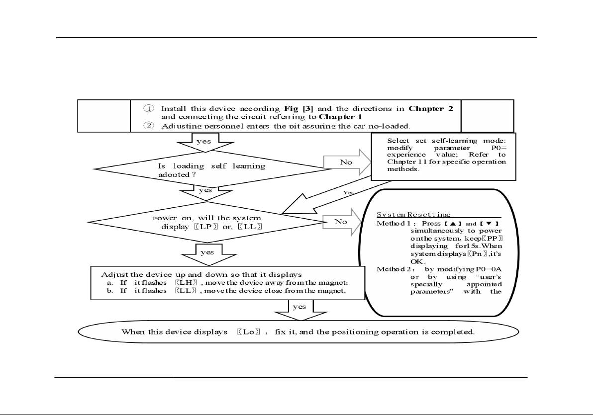
3、System Adjustment and Directions
①System Positioning Operation:
Technical File of the EWD-H-J3 Intelligent Elevator Load Weighing Device [User’s Guide] [V2.2]
Page5 of 15
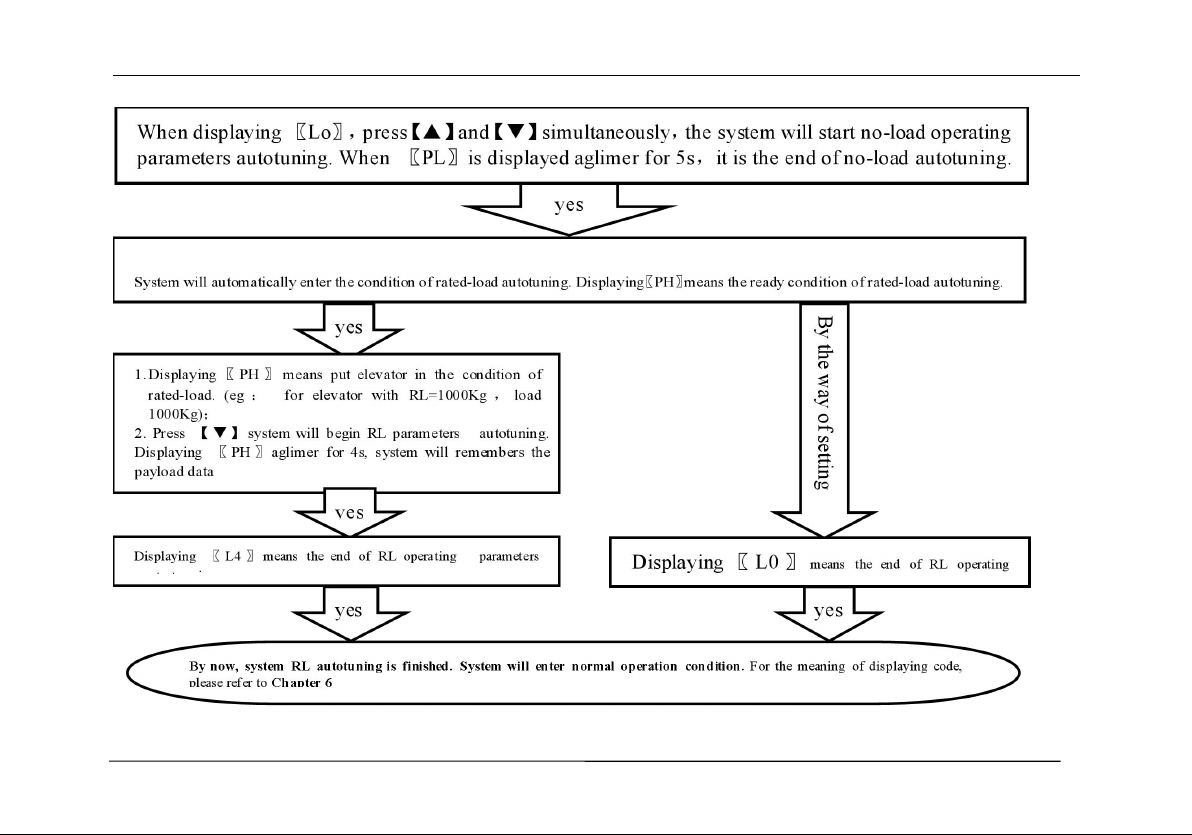
② No load and Rated Load Operation Parameters for Autotuning:
③System Adjustment under other conditions:

Technical File of the EWD-H-J3 Intelligent Elevator Load Weighing Device [User’s Guide]
Page6of15
For the following reason,it is necessary to modify the operating parameters of this device.
①
For elevator car decoration change
,
the dead weight of the moveable car platform changes
;
②
The car platform appears mechanical deformation
;
③The temperature difference between winter and summer has an unneglecting effect on the elastic coefficient of car platform
damping rubber;
④
The car platform appears damping rubber appears aging or deforming
;
⑤
The elevator overruns at the top or at the bottom
;
⑥The weighing device becomes slack at the fixing end.
Operation Parameters Adjustment and the Implication
4、System Operation Parameters Adjustment (Annotation:* represents for a hexadecimal value of
“0~9,A~F”)
①
Simultaneously press
【】
and
【】
on system control keypad to power on
,
this moment
〖
PP
〗
will be displayed aglimer,
that means entering operation parameters modifying status.
②Release【】and【】buttons,system will display〖P*〗and〖**〗alternately. 〖P*〗is an indication of system operation
parameters
;〖
**
〗
is the interior data value of
〖
P*
〗
.
③
When displaying
〖
P*
〗,
press
【】,
indication of system operation increases
;
press
【】,
indication decreases.
④
When displaying
〖
**
〗,
press
【 】,
data value increases
;
press
【】,
data value decreases.
⑤Release buttons,system displays operation indication and configuring data alternately.
⑥To modify other configuring datum, repeat the operation in item 3, item 4, item 5.
⑦
At the moment when system displays
〖
P*
〗,
Simultaneously press
【】
and
【】,
system will save modified datum for
future use. This moment, system displays〖Pn〗 for 1 second. System operation parameters modification of this time is completed.
Example:Modify parameter P2 to 16;
①
Simultaneously press
【】
and
【】
on system control keypad to power on
,
this moment
〖
PP
〗
will be displayed aglimer,
that means entering modifying status.
②Release【】and【】buttons,system will display〖P0〗and〖**〗aglimer
③
When displaying
〖
P0
〗,
press
【】
to increasing it to
〖
P2
〗;
④
Release button
【】,
system alternately displays
〖
P2
〗
and
〖
**
〗;
Technical File of the EWD-H-J3 Intelligent Elevator Load Weighing Device [User’s Guide] [V2.2]
Page7 of 15
⑤When displaying〖**〗,press【】or【】to regulate its value as〖16〗;
⑥
Release button
,
system alternately displays
〖
P2
〗
and
〖
16
〗;
⑦
At the moment when system displays
〖
P2
〗,
Simultaneously press
【】
and
【】,
system will save modified datum for future
use. This moment, system displays〖Pn〗for 1 second. System operation parameters modification is completed.
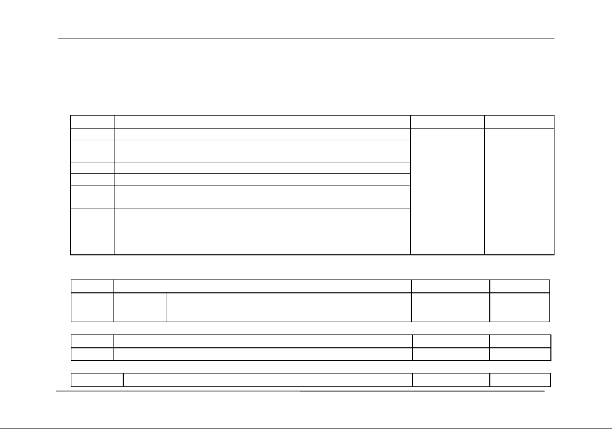
5、Implication of parameter P:
①Directions of Parameter P0 [System Operation Mode]:
Setting
Explanation
Default Setting
Normal Value
00
Normal Operation
01
00
This value will be
modified in the
course of
autotuning.
01
Sensor installing positioning, system no-load and rated-load autotuning
operation.
02
Specifying system no-load autotuning operation.
03
Specifying system Rated-load autotuning operation.
04
Select “20% rated load”autotuning operation,being convenient for users
special adjustment.
25~99
×0.1mm
For elevator with known “no-load→rated-load”compressing moveable car
platform damping rubber pad,it may be set manually. The system may be put
into use after system installation positioning. (This adjustment is very
convenient for elevator manufacturers. For more detail, refer to Chapter 10.)
②Directions of Parameter P1
[Hold input signal status setting and relay output condition setting]:
Setting
Explanation
Default Setting
User Setting
00
0-Stepped
output
0-P6 and P7 are short circuited, system output signal will be
held.
00 Stepped output,
short circuit for
holding
③Directions of Parameter P2 [Light-load parameter setting]:
Setting
Explanation
Default Setting
User Setting
00
~
30
Light load signal output
05
④
Directions of Parameter P3 [Light-load parameter setting]
:
Setting
Explanation
Default Setting
User Setting

Technical File of the EWD-H-J3 Intelligent Elevator Load Weighing Device [User’s Guide]
Page8of15
P2+1
~
60
Half-load signal output
30
⑤Directions of Parameter P4[Semi-load parameter setting]:
Setting
Explanation
Default Setting
User Setting
P3+1~90
Heavy-duty signal output
70
⑥
Directions of Parameter P5 [heavy-load parameter setting]
:
Setting
Explanation
Default Setting
User Setting
P4+1~99
Full-load signal output
90
⑦Directions of Parameter P6 [System overload coefficient]:
Setting
Explanation
Default Setting
User Setting
00~20
Load *105%, overload signal output
05
⑧
Directions of Parameter P7 [Operation Status setting of Solid state relay
“
J1
”
]
:
Setting
Explanation
Default Setting
User Setting
00~1F
Light-load action close out put
01(Light load
action close)
⑨
Directions of ParameterP8 [Operation Status setting of Solid state relay
“
J2
”
]
:
Setting
Explanation
Default Setting
User Setting
00~1F
Full-load action close out put
04(Full load action
close)
⑩Directions of Parameter P9 [Operation Status setting of Solid state relay “J3”]:
Setting
Explanation
Default Setting
User Setting
00~1F
Over-load action open output
1F(Over load
action open)
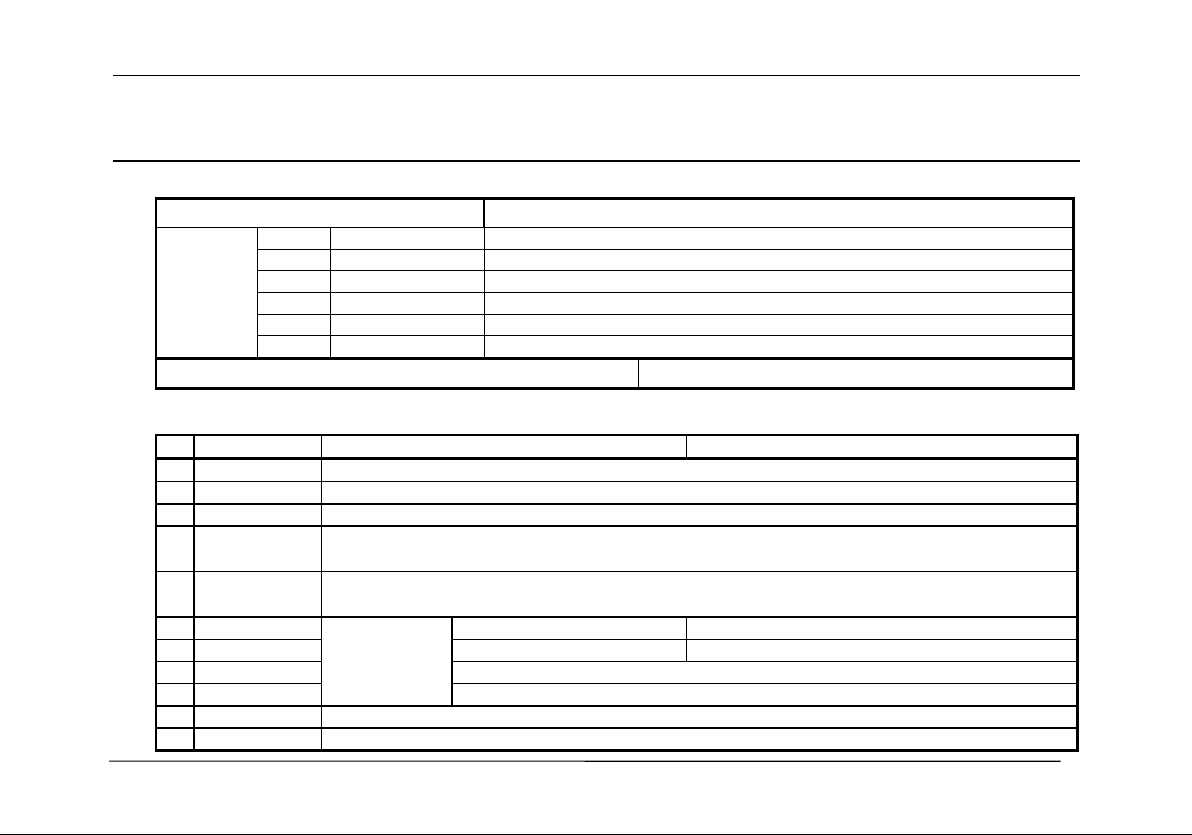
⑪Directions of Parameter D [Displacement-expanding Setting]:
Setting
Explanation
Default Setting
User Setting
01
~
03
Higher Bit
Lower Bit
01 displacement
closing 10mm valid
0-Load increases, displacement
approaches
1. Select sensor 0~9.9mm valid;
Technical File of the EWD-H-J3 Intelligent Elevator Load Weighing Device [User’s Guide] [V2.2]
Page9 of 15
Notice:①Select unindicated setting will lead to system abnormal operation.
②Even if auto-zeroing function is in use, autotuning operation should be done again in the course of periodical maintenance.
Explanation of Displaying Code:
6、System Normal Operation Code: (“W”is the present effective load)
Display Code
Indication
System
displays
〖
L*
〗
L0
No-load car
Output No-load signal
L1
Light-load car
Output Light-load signal
L2
Half-load car
Output Semi-load signal
L3
Heavy-load car
Output Heavy-load signal
L4
Full-load car
Output Rated-load signal
LF
Over-load car
Output Over-load signal
For user to save:the code of this elevator
Rated-load Compression: ㎜
7
、
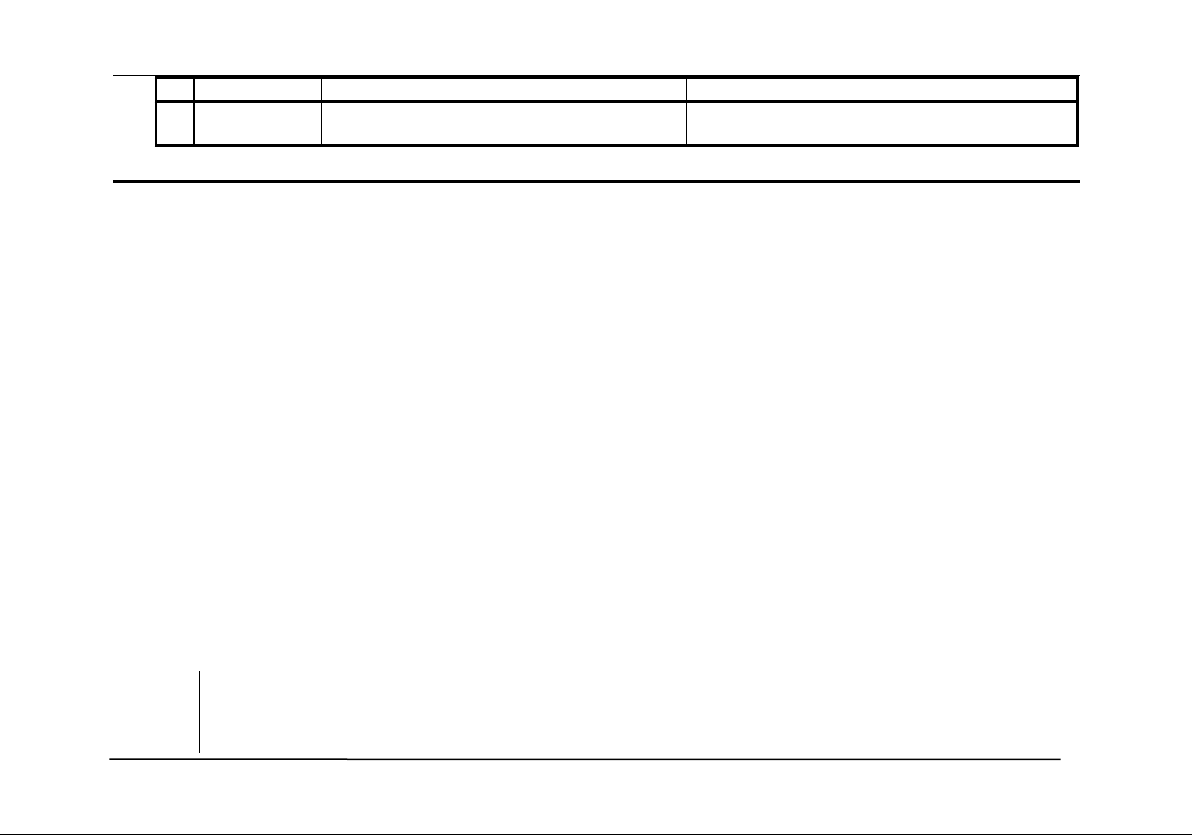
Code for Other Operation and Failures
Display Code
Indication
Solution
1
FY
System Startup
2
Pc
System Resetting
3
PP
Get into the status of operation parameters modification
4
PL
Autotuning No load parameters (Static Displaying represents preparative status,twinkling displaying
for the end of testing)
5
PH
Autotuning Rated load parameters (Static Displaying represents preparative status,twinkling displaying
for the end of testing)
6
LL
Installation and
positioning
Too big Positioning
Move this device closing to the magnet
7
LH
Too small Positioning
Move this device away from the magnet
8
Lo
Accurately Position
9
LP
Interior Auto Correction
10
P*
System Configuration Indication
11
Pn
Saved
Technical File of the EWD-H-J3 Intelligent Elevator Load Weighing Device [User’s Guide]
Page10of15
Display Code
Indication
Solution
12
EE
Variables at the bottom of the car overflow
Vibration damping rubber too soft, adjust the PD
parameters
How to do?
8
、
Brief Analysis of Other Conditions
:
①After installation of this weighing device, weighing signal changes in the course of operation?
The elevator load output value is not held after elevator starts, adjust the relative items of the inverter and
controller.
②After long-term of operation, system no load zeroing point appears larger deviation?
May be caused by the reason described in section 3,Chapter 3. Set system Autotuning mode to calibrate again
③After the elevator weighing is changed from heavy load to light load, heavy load signal is still displayed?
The movement of the moveable car platform is blocked, it is not reset after pressing. Solute the relevant
mechanic problems.
④System output signal doesn’t change linearly along with the change of load?
Check the structure of the moveable car platform,pay more attention that there should only be one pair of
damping rubber or spring moving relatively to the moveable car platform.
⑤During the system operation, analog output is abnormal or system resetting or speed-regulator cooperation is
abnormal?
It may be caused by system power source series interference. Select another group of power to supply the
system, or to provide an exterior power of AC/DC 24V/300mA to supply.
9
、
How to set an elevator with known
“
no-load
→
rated load
”
compression deformation
?
For example:The max “no-load→rated load”compression deformation of this elevator is 5.8mm.
Operat
ion
⒈Modify“P0=58”and save it. Refer to chapter 5;
⒉After system restarting,〖LP〗is displayed. Wait until〖LL〗,〖Lo〗or〖LH〗 is displayed;
⒊When the car is empty,adjust system installation position to make it display〖Lo〗,fasten it;

Technical File of the EWD-H-J3 Intelligent Elevator Load Weighing Device [User’s Guide] [V2.2]
Page11 of 15
⒋When〖Lo〗is displayed,press【▲】and【▼】simultaneously,system begins to autotune no-load
operation parameters;
⒌After〖PL〗is display aglimer for 5 second, the whole process of autotuning is finished.
10
、
How to do Re-Autotune operation for system?
Method 1:Simultaneously press【▲】and【▼】on system control panel to power on. This moment, system
aglimmer displays〖PP〗and 〖P-〗.Keep 15 seconds,system will display〖Pn〗.On that occasion,
all operation parameters reset to default settings.
Method 2:Modifying parameter P0=0A or user specified operation code will reset system immediately to
default status. But for users with specified code. The method is mentioned in Chapter 5.
11、How to modify output status of a system after autotuning is finished?
Modify the corresponding controlling parameters of parameter P respectively. The method is mentioned in
Chapter4.and 5.
12、How to adopt 20% rated load for rated load autotune?
Modify P0=04. After〖Lo〗positioning and no-load〖PL〗autotuning,in the period of system displaying
〖PH〗,load 20% of the rated load,press【 】,system displaying 〖L1〗means the end of adjustment. This
is an auxiliary method when 100% autotuning can be done.
13、The compression of car damping rubber exceeds the sensor inspection range?
Before autotuning, be assure to select “PD”=“02/03”and save it. Then, readjusting the installing position
of the sensor is OK (See parameter PD for more details).
14、
On adopting operation of
“
load increasing
,
displacement aloofing
”
method
?
Before autotuning, be assure to select “PD”= “1*” and save it. Then, readjusting the installing position
of the sensor is OK.
System Characteristics
15、Working principle of “EWD-H-J3”elevator weighing device

Technical File of the EWD-H-J3 Intelligent Elevator Load Weighing Device [User’s Guide]
Page12of15
With the development of elevator technology, the influence of elevator weighing device on its performance
has reached a point that cannot be ignored. High precision of elevator to weighing device,The demand of high
reliability and multi-function is imminent. With the development of sensor technology and microcomputer, Hall
sensors with high precision are used to detect The displacement of elevator car bottom due to the load is
changed. At the same time, the single chip microcomputer is used to deal with it scientifically, so that the device
can realize the change of elevator car Working function of effective load weighing.
16、Main property
⑴ Working in a contactless and inductive way. No mechanical movement. Solid-state relay outputs. Being
directly installed in the original place of overloading switch. No necessity of changing the mechanism of
elevator car.
⑵ The whole system is designed in the waterproof structure with small overall size, easy installation and
adjustment and simple structure.
⑶ Wide induction range, high accuracy positioning, intelligent temperature compensation making the range of
operating temperature wider.
⑷ The inner core consists of Hall sensor of high accuracy and single-chip microprocessor of high efficiency. All
parameters may be set on the field.
⑸ Adopting strong inductive magnet, improving the anti-interference capability of the system to the utmost.
⑹ Each set of products undergo a rigorous aging process to ensure reliable work.
(7)System based on mathematical equations for scientific computing, automatic detection error correction
⑻ On-site adjustment is easy, either by autotuning or by manual displacement setting.
(9)The independent development of the programmable output signal control method can be used for all kinds of
traction elevator with moveable car platform.
17、Technical specifications:
⒈
Application
Being applicable to all moveable car platform elevators,with an auto inspection range
of (2.00mm ≤car platform movement≤ 10.00mm); manual setting displacement

Technical File of the EWD-H-J3 Intelligent Elevator Load Weighing Device [User’s Guide] [V2.2]
Page13 of 15
range 2.5~9.9mm (relate to parameter PD)
⒉
Sensitivity
Elevator rated load/200 (With the rated load of 1T, it is 5.0Kg)
⒊
System Error
≤1.5%(5~40℃)
In the whole temperature range≤3.0%
⒋
Non-Linearity
≤1.0%
⒌
Output
Mode:
Solid-st
ate
Relay
Programmable
universal
signal
① 3/5 channel programmable output modes are: No load, light load,
semi full load, heavy load, rated load, overload (customer may set
the changing range freely).
②Each channel can be programmed as dynamic Close or Open contact.
③Contact Capacity:DC/AC 32V/15mA。
6
Working
Temperature:
-20~55℃
7
Relative
Humidity:
20%~99%RH
8
Reaction Time
≤0.25 Second
9
Power Supply:
AC/DC 24(±10%)V/150mA
10
Installation
Place:
Moveable car platform of elevator
11
Overall Size:
45×45×90 mm3
:The intension exceeding the limit parameters listed above may result in the abnormality
or permanent damage to the system.
Promise
⑴If this system appears any quality problem of product itself in 1 year after delivery, it will be replaced freely
(damage of the product seal will not be dealt with)。
⑵For any requirement of special functions, make it out by mail.

Technical File of the EWD-H-J3 Intelligent Elevator Load Weighing Device [User’s Guide]
Page14of15
⑶Any system abnormality in adjustment or operation, please contact our company directly.
Others
1.Accessory
Instruction Manual
1 copy
Fixing Screw set
2 sets
Inductive magnet [20×20×4mm3]
1 piece
2.address book:
029-88416613 85565714
029-85568478
7D, Block A, Olympic Building, 14th
Chang An North Road, Xi'an
029-85565714-886
710068
Technical support:18092639752 18092639750
