
Technical File of EWD-RLG-SJ3 Serial Intelligent Elevator Weighing Device [User’s Guide]
U s e r ’ s
EWD-RLG-SJ3
(V2.3)
DEVELOPED BY XIAN EXCELLENT ELECTROMECHANICAL CO.

Technical File of EWD-RLG-SJ3 Serial Intelligent Elevator Weighing Device [User’s Guide]
Page
2
of 36
Table of
Contents
Product Overview
1.“EWD-RLG-SJ3”weighing device main functional characteristics
………
Page 3
2.“EWD-RLG-SJ3”Working Principle
………
Page 3
3.Controller appearance and dimensions
………
Page 4
4.Weighing device controller interface description
……
Page 6
5.Sensor outside view
………
Page 8
Installation &
Adjustment
6.Install Method of Sensor and Controller
………
Page 8
7.System Adjustment and Explanation
………
Page 9
Working parameter
adjustment method
and meaning
8.Weighing device parameter adjustment method
………
Page 12
9.Explanation of the Meaning of Parameter P
………
Page 12
Indicating Code
Explanation
10.System normal operation code description
………
Page 16
11.Explanation of the Code of Other Operations and Fault
………
Page 16
How To Do?
12.Brief Analysis of Other Status
………
Page 17
13.How to re-do the "self-learning" operation of the weighing device?
………
Page 18
14.How to do Rated Load Self-learning by adopting 20% rated load?
………
Page 18
Weighing device
characteristics
16.Technical Specifications
………
Page
Promise
………
Page 20
Others
………
Page 20
Attached Drawings
[1]、[2]、[3]
………
Page 20
Attached Sheet
………
Page 20

Technical File of EWD-RLG-SJ3 Serial Intelligent Elevator Weighing Device [User’s Guide]
Page
3
of
Product Overview
“EWD-RLG-SJ3”Main Functional and Characteristic
:
⑴
1. A variety of intelligent sensors:
A. Select the ultra-thin "dish type" load intelligent sensor, without changing the drag cone sleeve rod, directly detect the change of
car load;
B. Choose "王" type tension intelligent sensor, more convenient installation.
C. Choose the ultra-thin "Type I" load intelligent sensor, without changing the drag cone sleeve rod, directly detect the change of
car load;
⑵ Weighing range is wide (effective load of 500Kg~5500 Kg),high-accuracy position,intelligent temperature compensation.
⑶ Electric property complies with the requirements of “International Electrotechnical Commission(IEC)”Standard.
⑷
Inner core consists of highly accurate load sensor and high performance single-chip micro-computer. All operation parameters
can be set on field.
⑸ Auto on-site measuring of various compensation methods, boosting requirement of high accuracy weighing signal of elevator
system.
⑹
System may do scientific calculation according to mathematical equations with the function of no-load auto zeroing
,
automatically modifying measuring error.
⑺ Directly displaying present effective load. Some types may directly measure dead weight of elevator car for the benefit of users.
⑻ Field adjustment may select 20% or 100% rate load self-learning method or load setting method , being easily
adjusted and operated.
⑼ Independent development of the method of Programmable Output Signal Control is suitable for all the requirement

Technical File of EWD-RLG-SJ3 Serial Intelligent Elevator Weighing Device [User’s Guide]
Page
4
of 36
of traction elevators with various kinds of fixed car platform.
⑽
Having the function of operation parameters auto modification
,
auto accommodation to multi methods of intelligent floor
compensation function,being applicable to traction elevators of less than 30 landings.
⑾ Distinctive design structure of sensor+ controller, only 2 connecting wires between sensor and controller making wiring simply.
⑿
The whole shoot starts from users’ point of view
,
easy installation and adjustment
,
decreasing users’ additional cost in use
,
high
ratio of performance to price.
一
. “EWD-RLG-SJ3”Installation method and working principle
:
With the development of elevator technology, the influence of elevator weighing device on its performance has reached
a point that cannot be ignored. Elevator to weighing device High precision, high reliability, multifunctional demand is
imminent. Today, with the continuous development of sensor technology and microcomputer, intelligent "tension" or "load"
sensor with high precision is used to detect electrical signals generated by load changes in elevator car boxes. The
sensor of the weighing device is installed at the head of the tow rope, and the sensor has its own signal transmission
cable; At the same time, the single chip microcomputer in the controller is used to carry out scientific calculation and
processing to realize the function of weighing the elevator car payload.
三
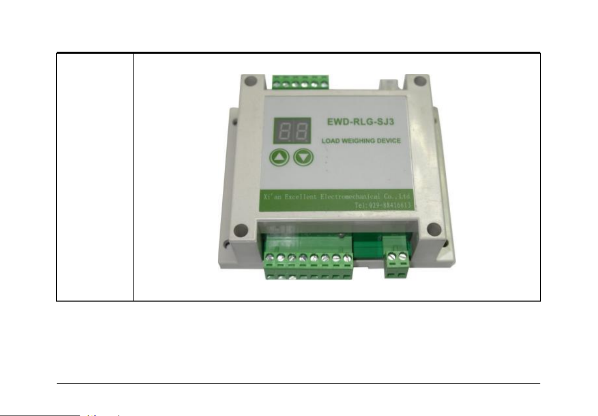
.Controller appearance and dimensions
:
Installed on
rope
EWD-RLG-SJ3
Application
Range
Apply to "bottom" fixed elevator, sensor default built-in 8 m cables, customers can
contact with our company custom cable according to the actual demand actual
length.
Technical File of EWD-RLG-SJ3 Serial Intelligent Elevator Weighing Device [User’s Guide]
Page
5
of
Controller
Appearance
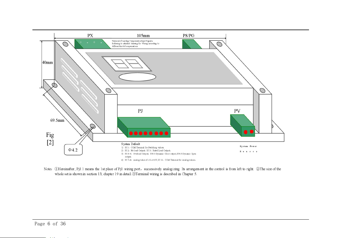
Controller Size Drawing:
Technical File of EWD-RLG-SJ3 Serial Intelligent Elevator Weighing Device [User’s Guide]
Page
6
of 36
Technical File of EWD-RLG-SJ3 Serial Intelligent Elevator Weighing Device [User’s Guide]
Page
7
of
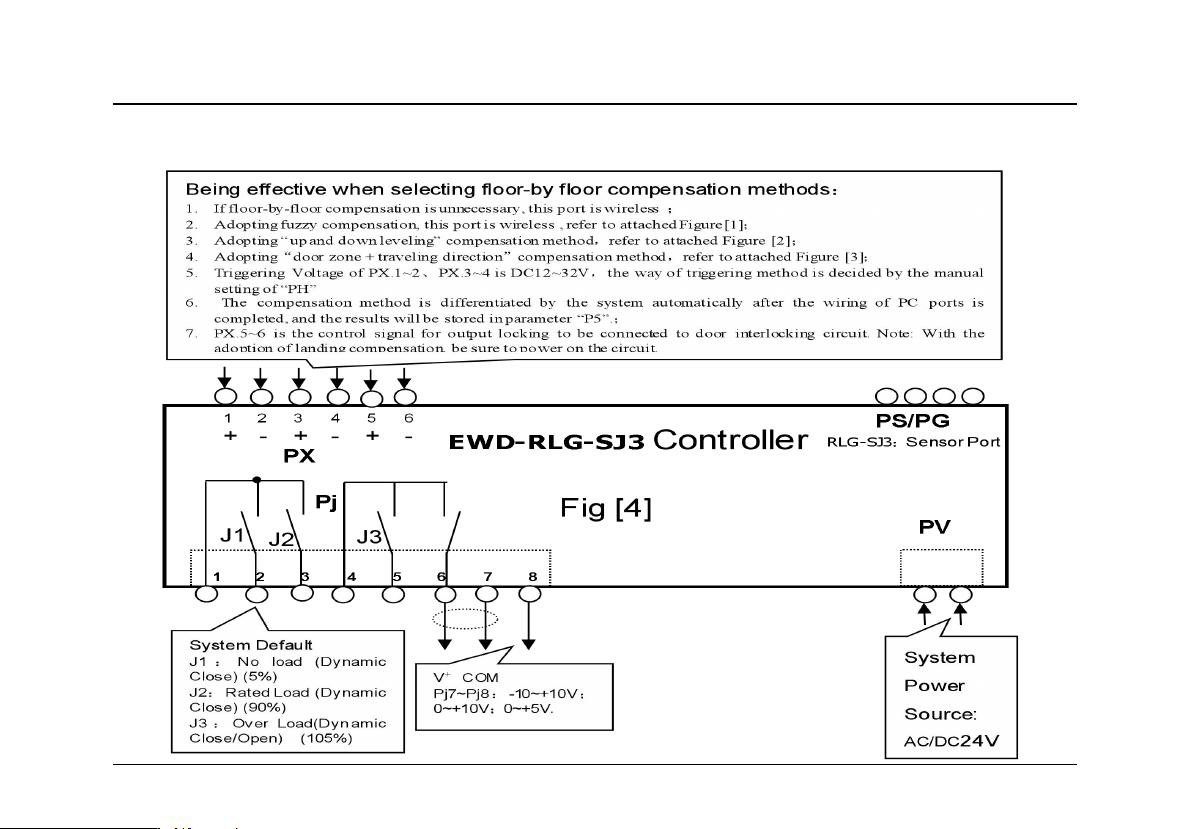
四.Weighing device controller interface description
Technical File of EWD-RLG-SJ3 Serial Intelligent Elevator Weighing Device [User’s Guide]
Page
8
of 36
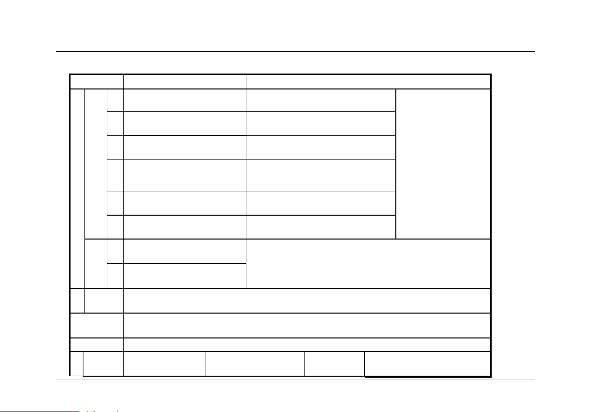
Detailed Explanation of the Controller Terminals:
Function
Explanation
PJ
Switching
.1
COM of J1~2 Relay
In coordination with Pj.2 ~ 4 to
produce effective logic
1. Effect:Be programmed
as“no load ~
overload”output signals to
participate in elevator
logic control
2.
Max loading Capacity:
DC/AC 48V/500mA
.2
J1 Relay Output Terminal
System Default“J1” : light load
Output;
.3
J2 Relay Output Terminal
System Default “J2” : Rated load
Output;
.4
COM of J3 Relay
In coordination with Pj.5 ~ 6 to
produce effective logic
.5
J3 Relay Output Terminal
System Default “J3” : Overload
Dynamic Close Output;
.6
J3 Relay Output Terminal
System Default “J3” : Overload
Dynamic Open Output;
Analog
.7
Analog Voltage Output: 0~
10V;-10~+10V;0~+5V
Being used for pre-torque compensation for driving system
.8
COM connected to analog common
terminal of speed regulator
P
X
5[+]~6[-]
Lock output signal control terminal. Be connected in system door lock signal circuit, pay
attention to connecting polarity.
PS/PG
For EWD-LG-SJ3:To Connect PS to the communication terminal of GW1 transducer
For EWD-RLG-SJ3:To Connect PG to the sensor along with signal cable
PV
System Power Supplying Terminal:AC/DC24V/200mA
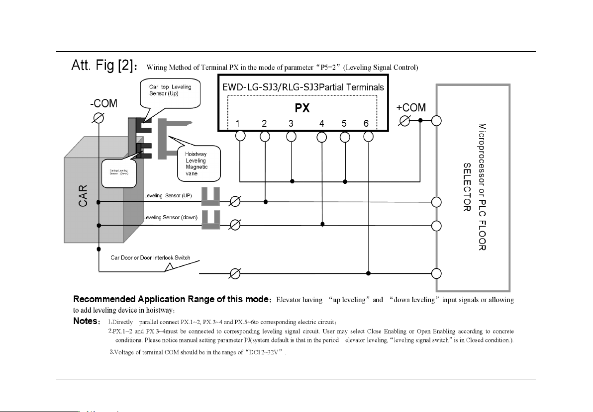
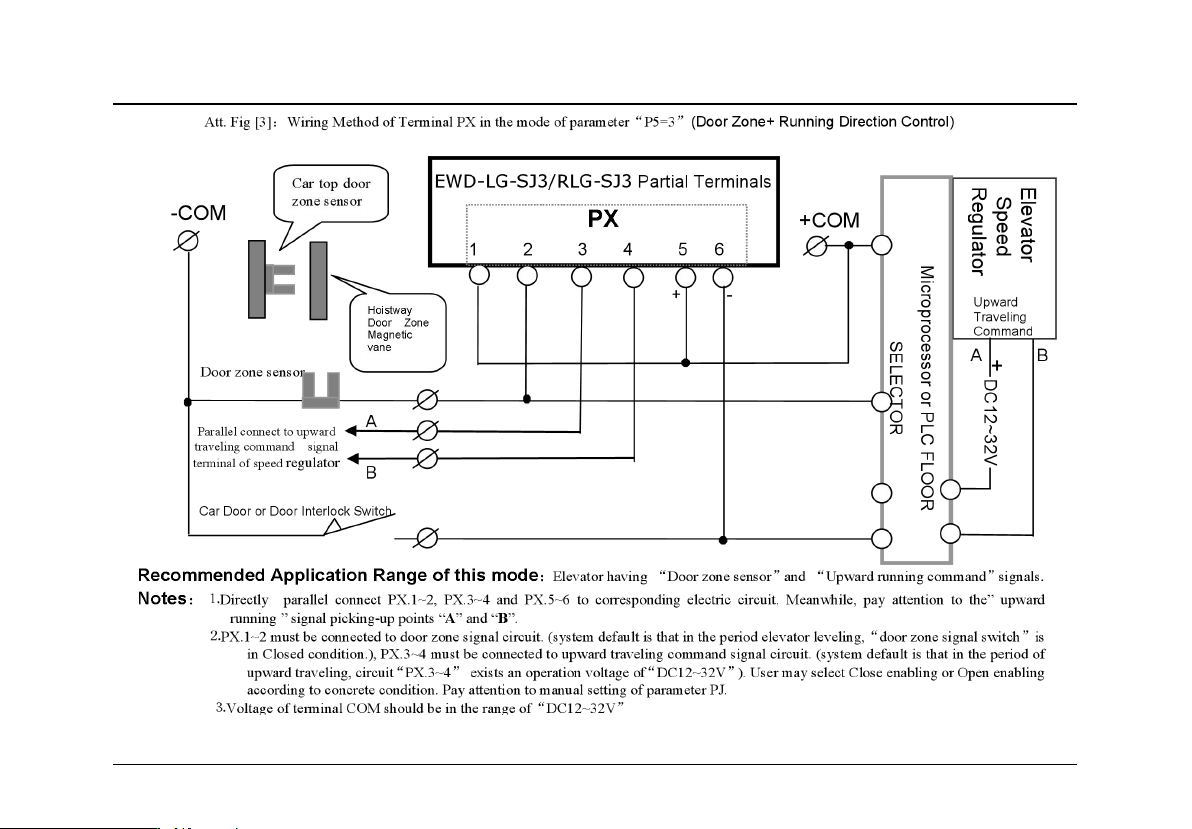
Parameter P5=2
Parameter P5=3
Parameter
P5=4
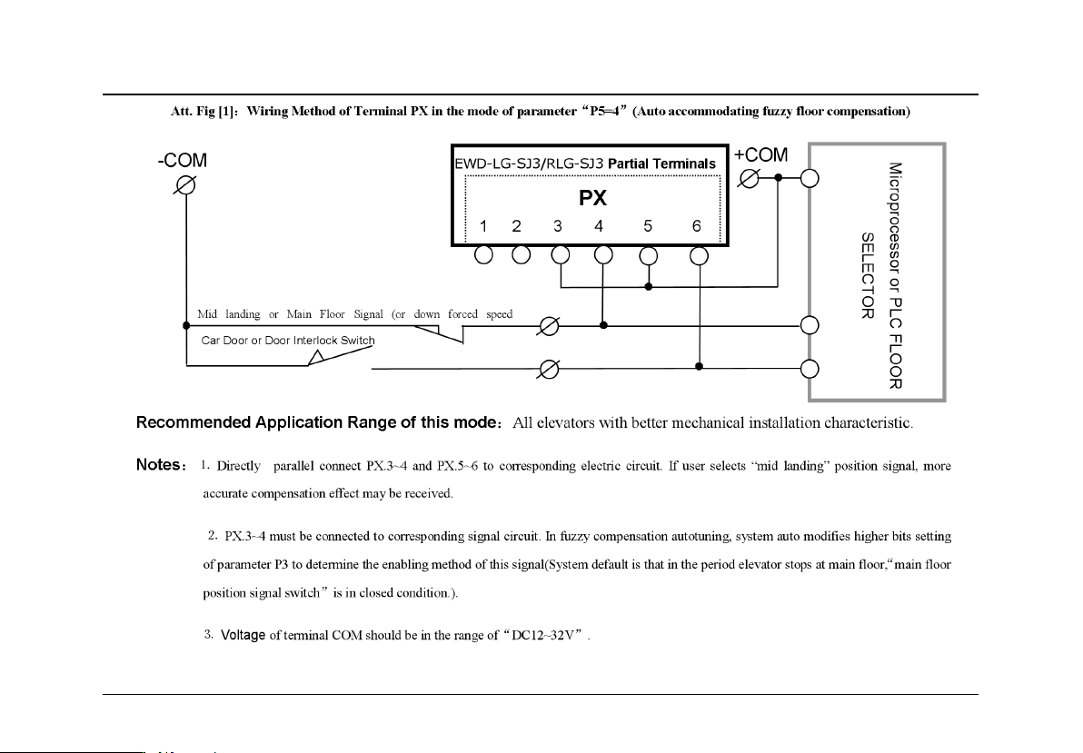
⒈No wiring: system unnecessary of landing
compensation;
Technical File of EWD-RLG-SJ3 Serial Intelligent Elevator Weighing Device [User’s Guide]
Page
9
of
P
X
⒉System may accurately control elevator
floor-by-floor compensation to interpolate the
dead weight floor error caused by cable, rope
and compensation cable;
⒊This terminal defaults positive skip of input
signal being effective and the enabling
method of PX3.1~2 、 PX3.3~4 depends on
parameter ”PD”.
⒋See attached figure for wiring.
1[+]~2[-]
Down leveling signal
( Up leveling Sensor)
Signal of Elevator entering
leveling zone or door zone
3[+]~4[-]
Up leveling signa
l (Down leveling Sens
or)
Elevator Up traveling Signal
Main floor
signal
①Absolutely don’t connect the output terminals (except “PV”) of this device to the
external power
source directly and the resulted permanent damage to the device is beyond our responsibility.
②Attention: As for the input signal of “PX” terminal,a requirement of polarity is needed, PX.1、3 and PM.1 are “+”,
and the corresponding circuit voltage should be “DC 12~32V”.
五
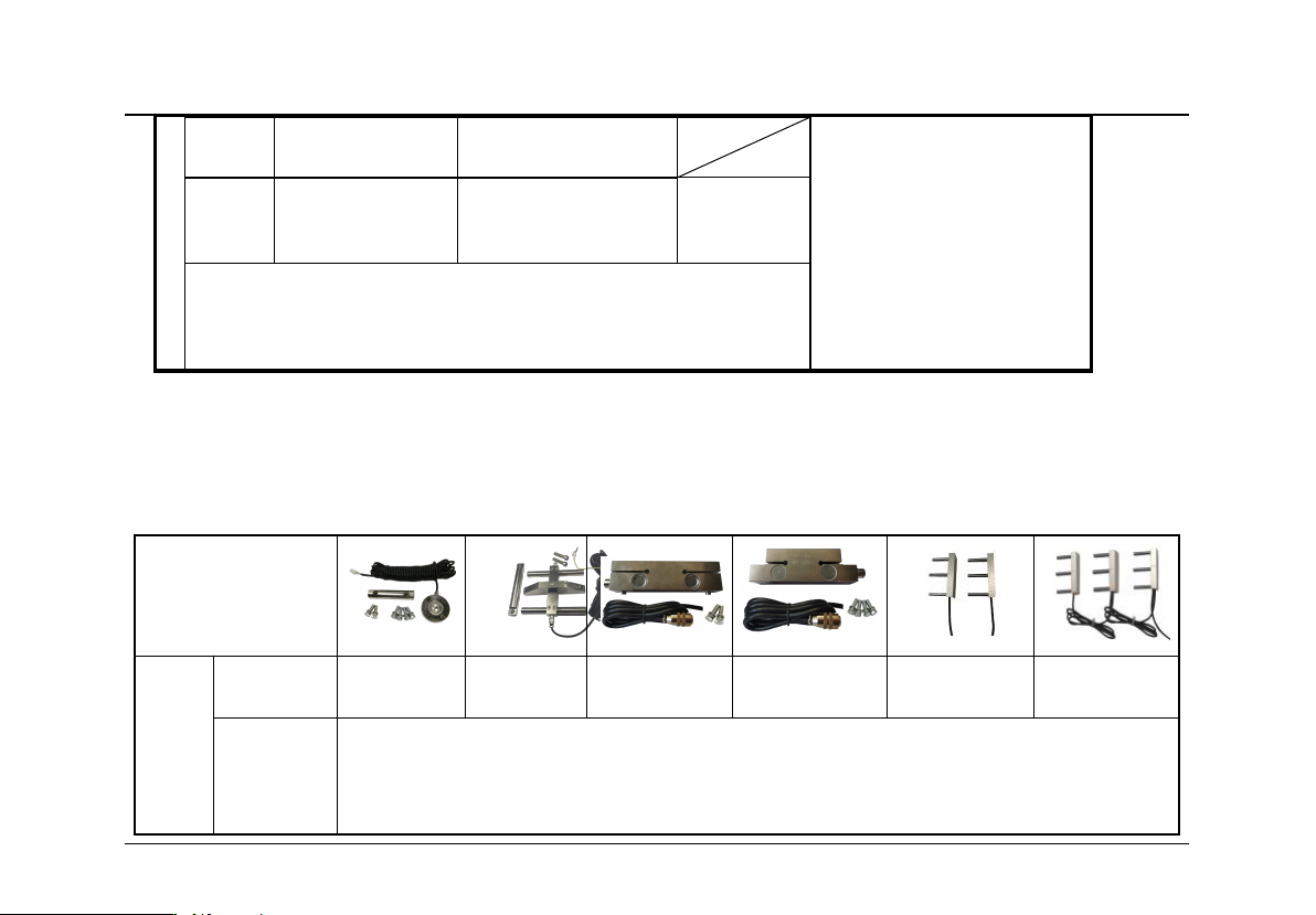
.Sensor Outside Drawing:
Outside Drawing
Product
Naming
Type
XCL-Y/862
5
XCL-ZL/W
XCL-T/A
XCL-T/B
XCL-ZL/P2
XCL-ZL/P3
Dimension
s and
mounting
methods
See attached page for details

Technical File of EWD-RLG-SJ3 Serial Intelligent Elevator Weighing Device [User’s Guide]
Page
10
of 36
Installation and Adjustment
6.Schematic Diagram for System Construction and Installing Method:
① Adjust the traction rope, make its consistent each pull
②A. "disc” type sensor according to the attached1.2, using "homemade taper sleeve splint"
installed in the elevator car traction taper sleeve parts;
B. "王" type sensor according to the attached 2.2, installed in the elevator car traction rope near
taper sleeve parts;
C. " 一 ” type sensor according to the attached"3.2,adopts "homemade taper sleeve splint"
installed in the elevator car traction taper sleeve parts;
③ Controller part should be installed in the engine room control cabinet, it is best not to close to
the elevator electric control system of transformer, governor and other equipment.In any case, sensor
and controller should be installed far away from the heat source
④ Connection between sensor and controller, had better not with 110 v and 220 v power supply
in the same wiring slot
⑤ The sensor connection port to connect to controller PG, PV according to system needs access
to the power cord at the same time, it is important to note the voltage level
⑥ Sure after checked, the system is powered on display controller shall have the corresponding
work
Technical File of EWD-RLG-SJ3 Serial Intelligent Elevator Weighing Device [User’s Guide]
Page
11
of
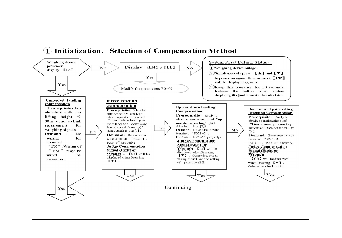
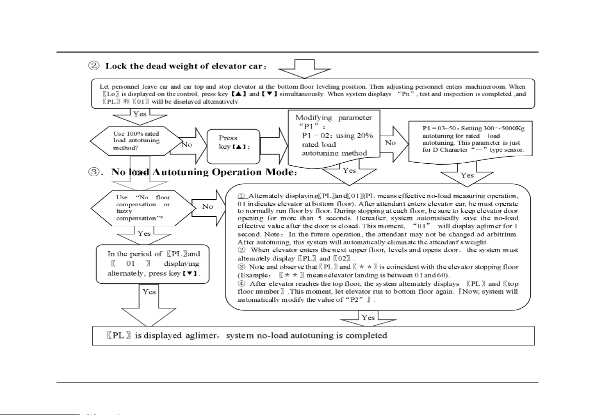
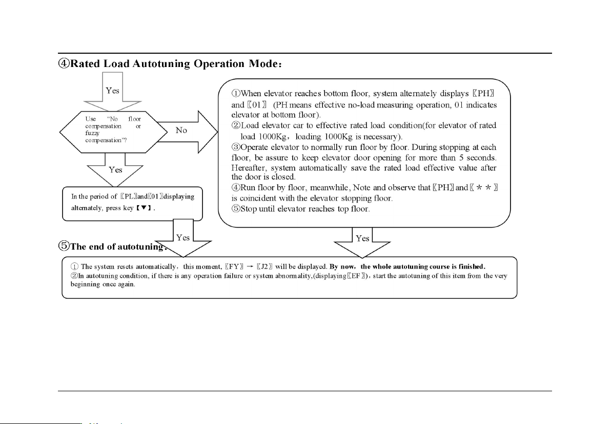
7.Adjustment Method and Description of the System ( Self-learning Operation)
Technical File of EWD-RLG-SJ3 Serial Intelligent Elevator Weighing Device [User’s Guide]
Page
12
of 36
Technical File of EWD-RLG-SJ3 Serial Intelligent Elevator Weighing Device [User’s Guide]
Page
13
of
System adjustment under other conditions:
For following reasons, the parameters of this system need re-modifying in the way described above.
Elevator car decoration changing causes its dead weight change.
1) Larger unbalance appears among traction ropes.

Technical File of EWD-RLG-SJ3 Serial Intelligent Elevator Weighing Device [User’s Guide]
Page
14
of 36
2) Sensor of weighing device becomes flexible.
3) Overrunning at the top or at the bottom occurs.
Operation Parameters Adjustment and the Implication
8.System Operation Parameters Adjustment (Annotation:* represents for a hexadecimal value of
“0~9,A~F”.)
①Simultaneously press 【▲】and【▼】on system control keypad to power on ,this moment 〖PP〗 will be displayed amplifier, that means
entering operation parameters modifying status.
②Release 【▲】and【▼】buttons,system will display〖P*〗and〖**〗alternately. 〖P*〗is an indication of system operation parameters;
〖**〗is the interior data value of〖P*〗.
③When displaying〖P*〗,press【▼】,indication of system operation increases;press 【▲】,indication decreases.
④When displaying〖**〗,press【▼】,data value increases;press 【▲】,data value decreases.
⑤Release buttons,system displays operation indication and configuring data alternately.
⑥To modify other configuring datum, repeat the operation in item 3, item 4, and item 5.
⑦At the moment when system displays 〖P*〗,Simultaneously press 【▲】and【▼】,system will save modified datum for future use. This
moment, system displays〖Pn〗 for 1 second. System operation parameters modification of this time is completed.
9.Implication of parameter P:Normally,it is unnecessary to modify parameter after “P0”. System may
automatically modify them in the course of self-learning.
① Directions of Parameter P0 [System Operation Mode]:
Setting
Explanation
Default Setting
Normal Value
00
Normal Operation (Automatically modify by system after
Self-learning.)
01
(Sensor Positioning)
00
System Auto Modifying

Technical File of EWD-RLG-SJ3 Serial Intelligent Elevator Weighing Device [User’s Guide]
Page
15
of
01
Sensor positioning, system self-learning
09
Options for dealing with abnormality when Selecting“王”type intelligent sensor.
0A
Forcibly set system settings as default values
② Directions of Parameter P1 [System Rated Load Setting Mode]:
Setting
Explanation
Default Setting
Normal Value
01/02或
05~55
×100Kg
01— Select“10% Rated load, floor by floor” Self-learning
02— Select“20% Rated load, floor by floor” Self-learning;
**—Select rated load setting mode(Not Recommended)Example:
“10”means rated load of 1000Kg. There is a certain error in
this method. Note
:
This mode is just for type “D” sensor.
01
(Rated load
self-learning)
③ Directions of Parameter P2 [The Highest Elevator Landing Setting Mode](Automatically modify them in the course of self-learning by system):
Setting
Explanation
Default Setting
Normal Value
01~32
Setting elevator landings:Selection of 01 means ceasing floor
compensation function. Input signal of PX is ineffective this time.
A0 (landings)
System automatically
modifies them in the
course of self-learning.
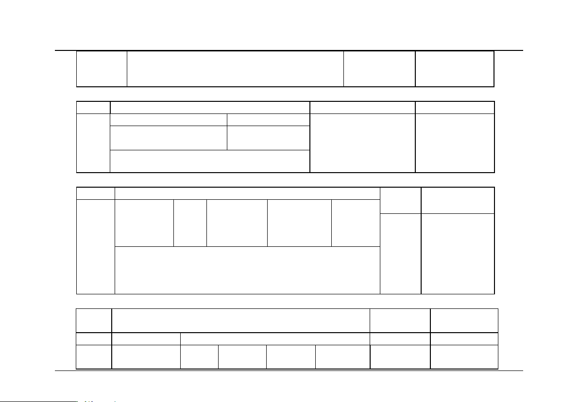
④Directions of Parameter P3 [Setting Elevator Shutdown at Main Floor]:
Setting
Explanation
Default Setting
Normal Value
01~19
Higher Bits
Lower Bits
0—“PX.5~6” effective for Low
Voltage Level;
1—“PX.5~6” effective for High
Voltage Level;
Setting elevator main
floor. Example:
Selecting 2 means
there is a basement
floor for this elevator.
01(landing)
Effective when
switched on, and
with the basement
floor is main floor.
System auto
modification in fuzzy
compensation
self-learning
Technical File of EWD-RLG-SJ3 Serial Intelligent Elevator Weighing Device [User’s Guide]
Page
16
of 36
Example:Selecting 12 means“PX5~6” effective for
Low Voltage Level and there is a basement floor for
this elevator.
⑤
Directions of Parameter
P4 [Time Parameter for Floor-by-floor Compensation]:
Setting
Explanation
Default Setting
Normal Value
00~99
Higher Bits
Lower Bits
12
Anti-interference protection
time of each floor is 2.0
seconds;Control Factor of
fuzzy compensation is 2.
Anti-interference protection time of each
floor : 0~9×0.5 Second;
Control Factor of fuzzy
compensation:0~3
0-Not Enabling protection time
⑥ Directions of Parameter P5 [Selection of Floor compensation input signal function] (Automatically modify in the period of self-learning by system):
Setting
Explanation
Default
Setting
Normal Value
00~03
00
Allow auto deciding
compensation
method
01
Disable
02
up/down leveling
step counting
control
03
Door zone + running
direction Control
04
Fuzzy
compensatio
n
00
(Auto
Measuring)
Auto modified by
system in the period
of 〖Lo〗displaying.
Notes:⒈ See Section 1, Chapter 8 and attached drawings for more details;
⒉ Elevator of serial communication control may use ”03” or ”04’ operation method.
Running direction Signal may be parallel connected to the forward rotation
command signal of the SPECIFIED inverter.
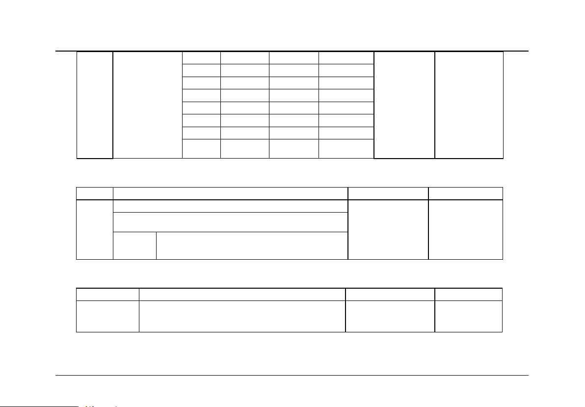
⑦ Directions of Parameter
P6 [Logic condition Setting Relay“J1”, “J2”, “J3”]:
Setting
Explanation
Default
Setting
Normal Value
Higher Bits
Lower Bits
0---
Selecting 0~10V
Contact
Status
J3
J2
J1
20
Technical File of EWD-RLG-SJ3 Serial Intelligent Elevator Weighing Device [User’s Guide]
Page
17
of
00~17
1---
Selecting 10~0V
2---
Selecting -10~10V
3---
Selecting +10~-10V
4---
Selecting 0~-+5V
(Relay
Dynamic
Close output,
analog output
of 0~10V is
effective)
0
Dynamic Close
Dynamic Close
Dynamic Close
1
Dynamic Close
Dynamic Close
Dynamic Open
2
Dynamic Close
Dynamic Open
Dynamic Close
3
Dynamic Close
Dynamic Open
Dynamic Open
4
Dynamic Open
Dynamic Close
Dynamic Close
5
Dynamic Open
Dynamic Close
Dynamic Open
6
Dynamic Open
Dynamic Open
Dynamic Close
7
Dynamic Open
Dynamic Open
Dynamic Open
⑧ Directions of Parameter P7 [Setting Relay“J1”Operation Range]:
Setting
Explanation
Default Setting
Normal Value
00~99
When Load≥ Rated load×P7%,“J1”signal is output.
05
Setting J1:
actuating for 05%
Rated Load
00~99:Actuating for 0~99% rated load
Example
P7=80:For effective load of 1T,system
actuates at 800Kg
⑨ Directions of Parameter P8 [Setting Relay“J2”Operation Range]:
Setting
Explanation
Default Setting
Normal Value
The same as
P7
The same as P7:
When load≥Rated Load×P8%,output “J2”signal
90
Setting“J2” 90% rated load
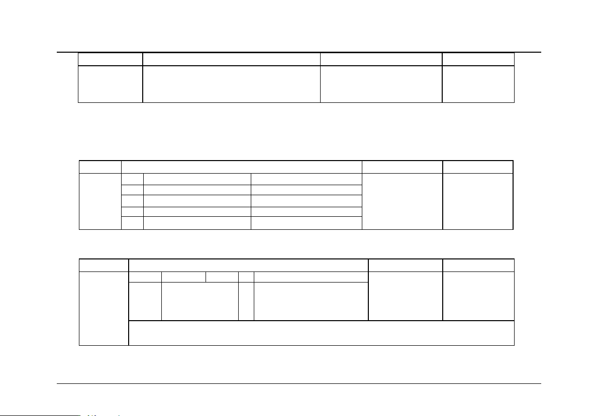
⑩
Directions of Parameter
P9 [
Setting Relay“J3”Operation Range
]:
Technical File of EWD-RLG-SJ3 Serial Intelligent Elevator Weighing Device [User’s Guide]
Page
18
of 36
Setting
Explanation
Default Setting
Normal Value
The same as
P7
The same as P7:
When load≥Rated Load×P9%,output
“J3”signal
A5
Setting“J3”, system actuates at
105% rated load
○11
Directions of Parameter PA
[No-Load Auto Zeroing Time Interval]:
○12
Directions of Parameter PB
[Detaining Time of No-Load Auto Zeroing]:
○13
Directions of Parameter PC [No load Auto Zeroing Error Range]:
○14
Directions of Parameter PD [Characteristics of Compensation Terminals]:
Setting
Explanation
Default Setting
Normal Value
00~03
PX.1~2
PX.3~4
00
PX.1~2、PX.3~4
Effective for High Voltage
Level
00
Effective for High Voltage Level
Effective for High Voltage Level
01
Effective for Low Voltage Level
Effective for High Voltage Level
02
Effective for High Voltage Level
Effective for Low Voltage Level
03
Effective for Low Voltage Level
Effective for Low Voltage Level
○15
Directions of Parameter PE [Selection of Sensor Parameters]:
Setting
Explanation
Default Setting
Normal Value
80~90
D7~D4
D3
D2
D1
D0
84
Standard Sensor , 2
gain-Levels for
selection
Sensor Gain
Adjustment
0 ~ 3 gain-Levels for
selection
0-Standard Sensor
1-Modification of “Convex” type
stress sensor picking-up
abnormality.
Recommendation:Normally, users don’t need to adjust this parameter. Any dissidence, contact
with the manufacturer directly.
Attentions: ① When selecting not indicated settings, system will not normally operate.
② No load auto zeroing parameters PA, PB and PC should be used cautiously because of the cause variety of elevator
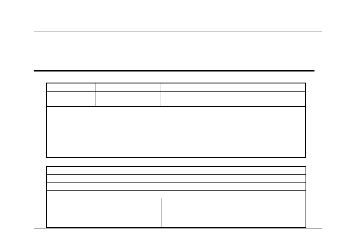
Technical File of EWD-RLG-SJ3 Serial Intelligent Elevator Weighing Device [User’s Guide]
Page
19
of
no load point drifting. It is recommended for the user to allow or forbid this function according the concrete conditions.
③
Even if No load auto zeroing operation enabled,in the course of elevator periodical maintenance,self-learning operation
of this system should be redone without exception.
Explanation of Displaying Code:
10.System Normal Operation Code:
〖J0〗
〖J1〗
〖J2〗
〖J3〗
No Relay Output
RelayJ1 Output
RelayJ2 Output
RelayJ2 Output
Default 5% of Rated Load
Default 90% of Rated Load
Default 105% of Rated Load
1. Displaying “HJ※※※※”when pressing 【 ▲ 】 button indicates present car effective load. For instance,
displaying“HJ0520 ”indicates the load of 0520㎏.
2. Displaying “.※. ※. ” when pressing【▼】button or in the course of landing changing indicates present system compensating
landing. Adjusting Personnel may judge whether system compensating landing tracing is right or not by its numerical value.
Note: This option is just for floor-by floor compensation method.
3. Displaying “0.0.”in fuzzy compensation indicates compensation is effective. Displaying “0.1.”indicates elevator entering
modifying zone.
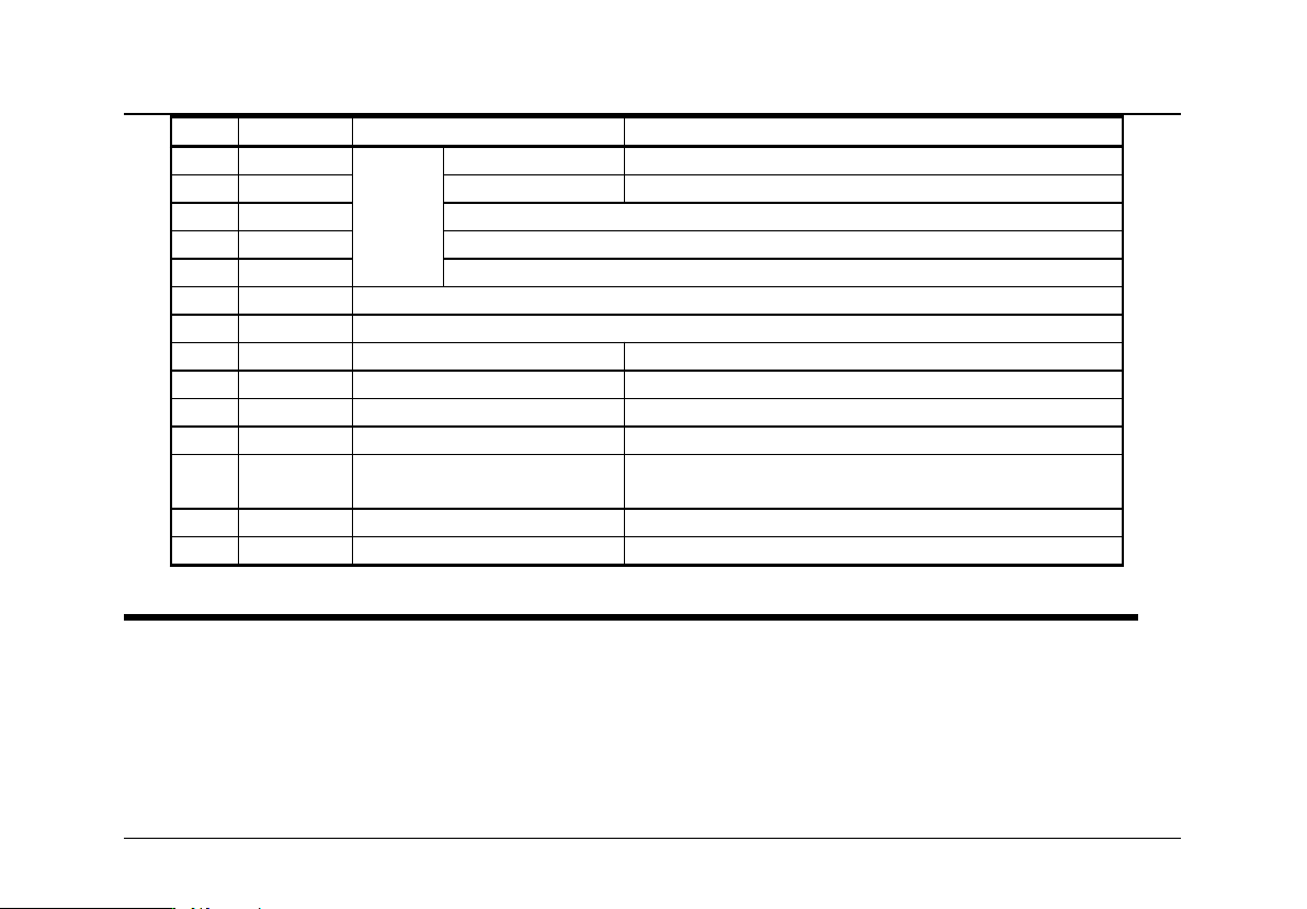
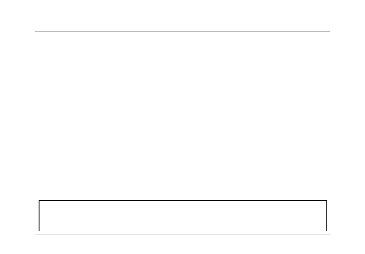
11.Code for Other Operation and Failures
Display Code
Indication
Solution
1
FY
System Startup
2
PC
Sensor Resetting
3
PP
Get into the status of operation parameters modification
4
PL
self-learning No load
parameters
(Still Displaying indicates preparation status,aglimmer
displaying indicates the end of inspection)
5
PH
self-learning Rated load
parameters
Technical File of EWD-RLG-SJ3 Serial Intelligent Elevator Weighing Device [User’s Guide]
Page
20
of 36
Display Code
Indication
Solution
6
LL
Installation
and
positioning
Too big Positioning
Sensor having no load
7
LH
Too small Positioning
Sensor overload
8
Lo
Accurately Position
9
LP
Interior Auto Correction
10
LY
Forcibly skip sensor interior auto correction
11
P*
System Configuration Indication
12
Pn
Saved
13
EA
Saving Failure
Modifying operation parameters again
14
EJ
Without this system setting
Check system settings
15
EH
Applied Overflowing Pressure
Sensor pressure may beyond its withstanding range
16
EL
Applied Insufficient Pressure
Sensor being not pressed
17
EE
No landing of this code
Make certain PC signals abnormality or no load self-learning normal
or not
18
EF
Memorizing abnormally
Repeat this operation.
19
ES
Communication Failure
Carefully check wiring between sensor and control.
How to do?
12.Brief Analysis of Other Conditions
:
⑴Bad system Operation Stability with the main indication of large output fluctuation in the condition of fixed load and
elevator motionless
?
Check if PV power supply source satisfy system requirements?
⑵After long-term of operation, system no load zeroing point appears larger deviation?

Technical File of EWD-RLG-SJ3 Serial Intelligent Elevator Weighing Device [User’s Guide]
Page
21
of
Please set up the system self-learning mode to calibration,or startup parameter“PA≠0” to realize the function of system no load
auto zeroing.
⑶System displaying failure code〖EE〗 ?
Incorrect Input signal of terminal PX on the control or unreasonably setting.
⑷
When selecting floor indication step counting control method
,
floor-by-floor compensation consistency is bad
?
Whether up or down landing signals or leveling signal is normally wiring
,
Setting of parameter P5 is reasonable?
⑸Traveling Up and down with the same load and stopping at the same floor, but the weighing result is different?
Lift rope pull is not symmetrical,adjust please.
Elevator guide shoes are too tightened
,
running friction is large. It is recommended to adjust or modify relevant
mechanical
part to make it move flexible
,
then operate the system to Self-learning again.
⑹System output signal doesn’t change linearly along with load?
Maybe system sensor is damaged.
⑺
How to descry present effective load of elevator car
?
In the period of system normal operation, press button
【 】
.This moment, system displays
〖
HJ
〗
→
〖
**
〗
→
〖
**
〗
.For
example :displaying 〖HJ〗→〖09〗→〖50〗 indicates a car with rated load of 1000 Kg presently bearing an effective
load of 950Kg.
If elevator effective load is not 1000 Kg
,
it may be decided after system self-learning operation is finished by modifying
parameter“P1”.
Because of various impacts from outer environment,displayed data may fluctuate in a small scope.
⑻When elevator is motionless, weighing signal is normal. But in the course of door opening, it is abnormal?
The elevator door dynamic weighing device generates the relative weight deviation of the car, and the output signal of the door
opening and closing relay plus the door lock signal can be used to participate in the PM locking control of the weighing
device.
Technical File of EWD-RLG-SJ3 Serial Intelligent Elevator Weighing Device [User’s Guide]
Page
22
of 36
⑼
During system operation, analog output is abnormal, repeatedly resetting or abnormal coordination with speed regulator
?
May be caused by crossing and interfering system power source. Select another set of power source to supply power to system
,
or equip AC/DC 24V/300mA exterior power source to supply power.
13.How to Repeat doing Self-learning operation for system?
Method 1:Simultaneously press【▲】and【▼】on system control panel to power on. This moment, system
aglimmer displays〖PP〗and 〖P-〗.Keep 10 seconds,system will display〖Pn〗.On that occasion,
all operation parameters reset to default settings.
Method 2:Modifying parameter P0=0A will reset system immediately to default status. But for users with
specified code, it is necessary to modify parameter P0 as appointed code. Detailed operation is
described in chapter 8.
14.How to adopt 20% rated load for rated load Self-learning?
After system displaying 〖 Lo 〗 , modify parameter“P1=02”.Do no load self-learning operation as
described in chapter 7. In the period of displaying〖PH〗,load elevator car with a weight equal to 20%
of rated load to do rated load self-learning operation. When operation is finished,〖L1〗is displayed.
15.Technical Specifications:
⒈
Application
Suitable for all traction, hydraulic, strong drive elevator use (load range depends on sensor
range)
⒉
Floor
Compensation:
Auto accommodating to the following compensation methods: ①Up and Down leveling; ②Up command +
door zone; ③Fuzzy and intelligent.
Technical File of EWD-RLG-SJ3 Serial Intelligent Elevator Weighing Device [User’s Guide]
Page
23
of
⒊
Sensitivity
Elevator Rated Capacity/200 (Example: The rated capacity is 1000 ㎏, and the sensitivity
is 5 ㎏ ) [This data may be affected by elevator mechanical performance.]
⒋
System Error
≤0.5%(-20~55℃)
⒌
Non-Linearity
≤0.5%
⒍
Compensation
The method of circuit parallel connection is applicable to the signal source system of
DC12~32V.Also, the interior fault of this system doesn’t affect the original operation mode
of elevator.
⒎
Output
Mode
Relay
Programmable
universal signal
①3-channel programmable output modes are: No load,full load and
overload (customer may set the changing range freely).
②Each channel can be programmed as dynamic Close or Open contact.
③Contact Capacity: DC/AC 48V/100mA
Analogue
quantity
Overall Compensation Range 0~10V, -10V~+10V, 0V~+5V
⒏
Ambient Temperature
Temperature:-20~55℃
⒐
Relative Humidity
20%
~
90
%
RH
⒑
Reaction Time
≤0.5Second,The communication distance between the intelligent and the control is 0~400m.
⒒
Power Supply:
AC/DC24(±10%)V/200mA
⒓
Installation
Place
Sensor Section:At the place of traction rope shackle
Controller Section:Control Cabinet in machineroom. See the figure 3 for installing dimension.
⒔
Overall Size:
Sensor Section:See the attached sheet
;
Controller Section
:
115×90×40 mm
3
Note:If the strength exceeds the limit parameters listed above, it may lead to abnormal operation or permanent
damage of the weighing device.

Technical File of EWD-RLG-SJ3 Serial Intelligent Elevator Weighing Device [User’s Guide]
Page
24
of 36
Promise
⑴If this system appears any quality problem of product itself in 1 year after delivery, it will be
replaced freely(damage of the product seal will not be dealt with)。
⑵For any requirement of special functions, make it out by mail.
⑶Any system abnormality in adjustment or operation, please contact our company directly.
Others:
其它
Technical Support:0086-18092639752 0086-18092639750
⒈Packing List::
Controller
1set
Φ4×20 Fastening Screw sets
4sets
Sensor
1set
Sensor attachment
1set
Manual
1piece
⒉Address book::
Xi’AN EXCELLENT ELECTROMECHANICAL CO.,LTD
:
(029)88416613 85565714
(029)85568478
Address:7D,Block A, Olympic Building,
14th Chang An North Road, Xi'an, Shaa
nxi,China
Technical File of EWD-RLG-SJ3 Serial Intelligent Elevator Weighing Device [User’s Guide]
Page
25
of
Technical File of EWD-RLG-SJ3 Serial Intelligent Elevator Weighing Device [User’s Guide]
Page
26
of 36
Technical File of EWD-RLG-SJ3 Serial Intelligent Elevator Weighing Device [User’s Guide]
Page
27
of
Technical File of EWD-RLG-SJ3 Serial Intelligent Elevator Weighing Device [User’s Guide]
Page
28
of 36
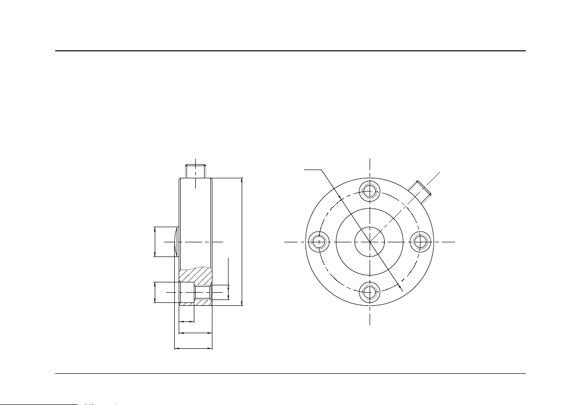
Φ68
25
10
22
4-Φ14
4-M
1
0
Φ86
Φ20
Attached page
:
Load cell / tension sensor dimensions and installation
1. XCL-Y/8625 type Intelligent loading Sensor size and installation method
1.1 Sensor size diagram: ( Measuring Range:12KN、22KN、30KN、40KN、50KN、70KN)
Technical File of EWD-RLG-SJ3 Serial Intelligent Elevator Weighing Device [User’s Guide]
Page
29
of
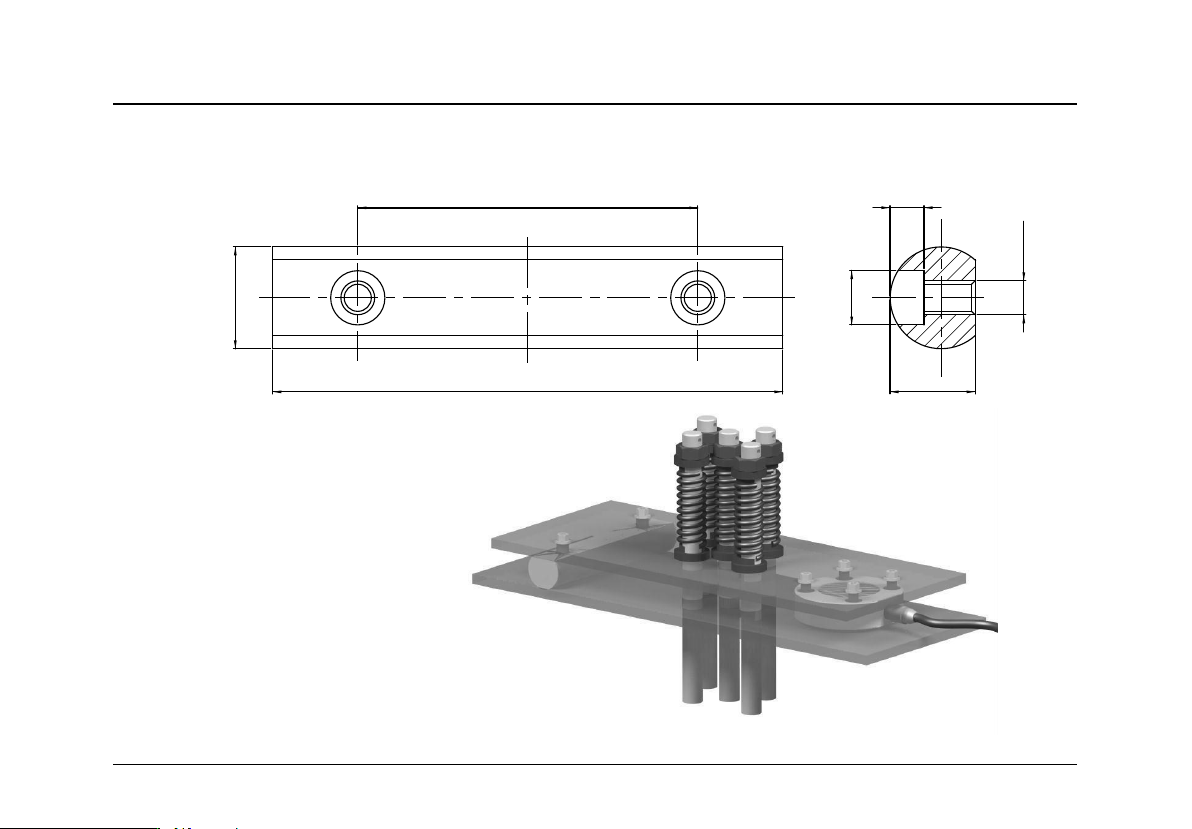
100
150
Φ
30
25
10
2-
Φ
16
2-M10
Size drawing of pressure rod
1.2 Installation Method
Technical File of EWD-RLG-SJ3 Serial Intelligent Elevator Weighing Device [User’s Guide]
Page
30
of 36
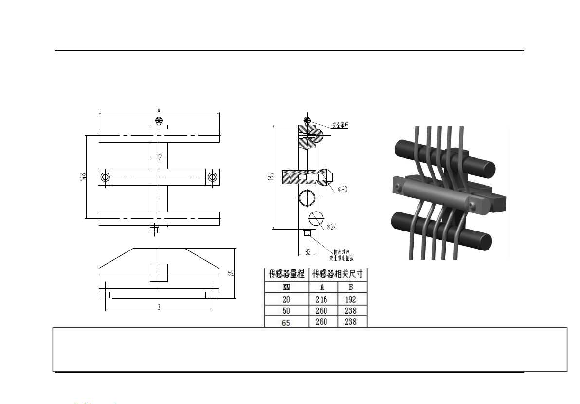
2. XCL-ZL/DW type Intelligent loading Sensor size and installation method
2.1 Sensor size diagram 2.2 Installation Method
Note: During installation, be sure to use Ø6 wire rope to connect the safety ring and secure it on the support of
the tractor, in case the sensor falls off during installation and debugging, to ensure personal safety!
Technical File of EWD-RLG-SJ3 Serial Intelligent Elevator Weighing Device [User’s Guide]
Page
31
of
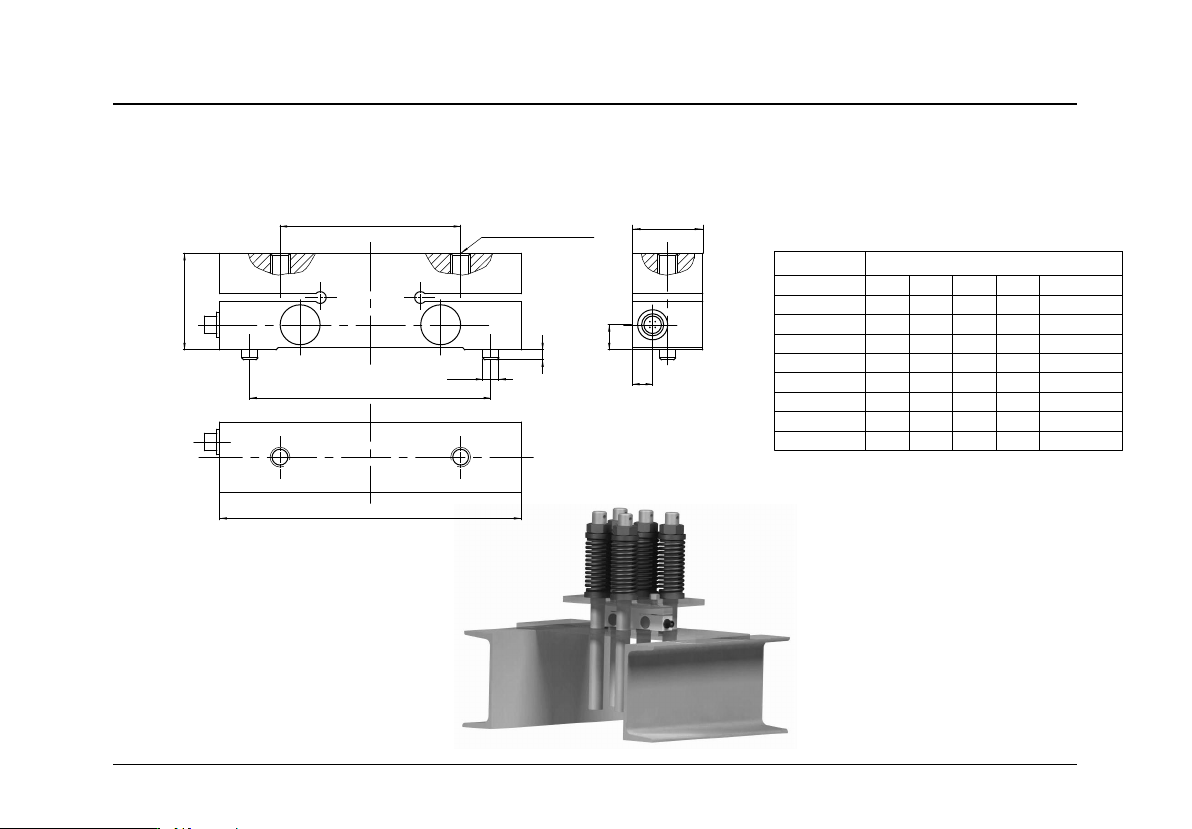
3. XCL-T/A type Intelligent loading Sensor size and installation method
3.1 Sensor size diagram
3.2 Installation Method
150
C
90
H
B
120
5
2-
Φ
8
2-M10(螺纹孔深度)
A
传感器量程 传感器相关尺寸
KN A B C
螺纹孔深度
H
10
15
20
30
50
70
100
150
25 8 12.5
通孔
41
25 8 12.5
通孔
41
25
8
12.5 通孔41
35 10 12.5
通孔
48
35 10 12.5
通孔
48
35 8 17 1860
35 8 1760
35 8 2170
18
18
Technical File of EWD-RLG-SJ3 Serial Intelligent Elevator Weighing Device [User’s Guide]
Page
32
of 36
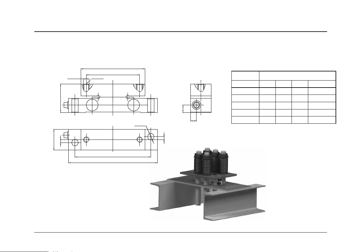
4. XCL-T/B type Intelligent loading Sensor size and installation method
4.1 Sensor size diagram
4.2 Installation Method
150
128
108
90
H
35
5
2-
Φ
11
A
B
2-M10
5
螺纹孔深度
传感器量程 传感器相关尺寸
KN A B
螺纹孔深度
H
30
50
70
100
150
10 12.5
通孔
48
10 12.5 通孔48
8
17
1860
8 17 1860
8 17 1870
Technical File of EWD-RLG-SJ3 Serial Intelligent Elevator Weighing Device [User’s Guide]
Page
33
of
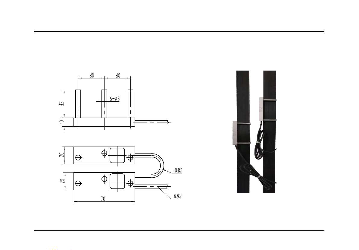
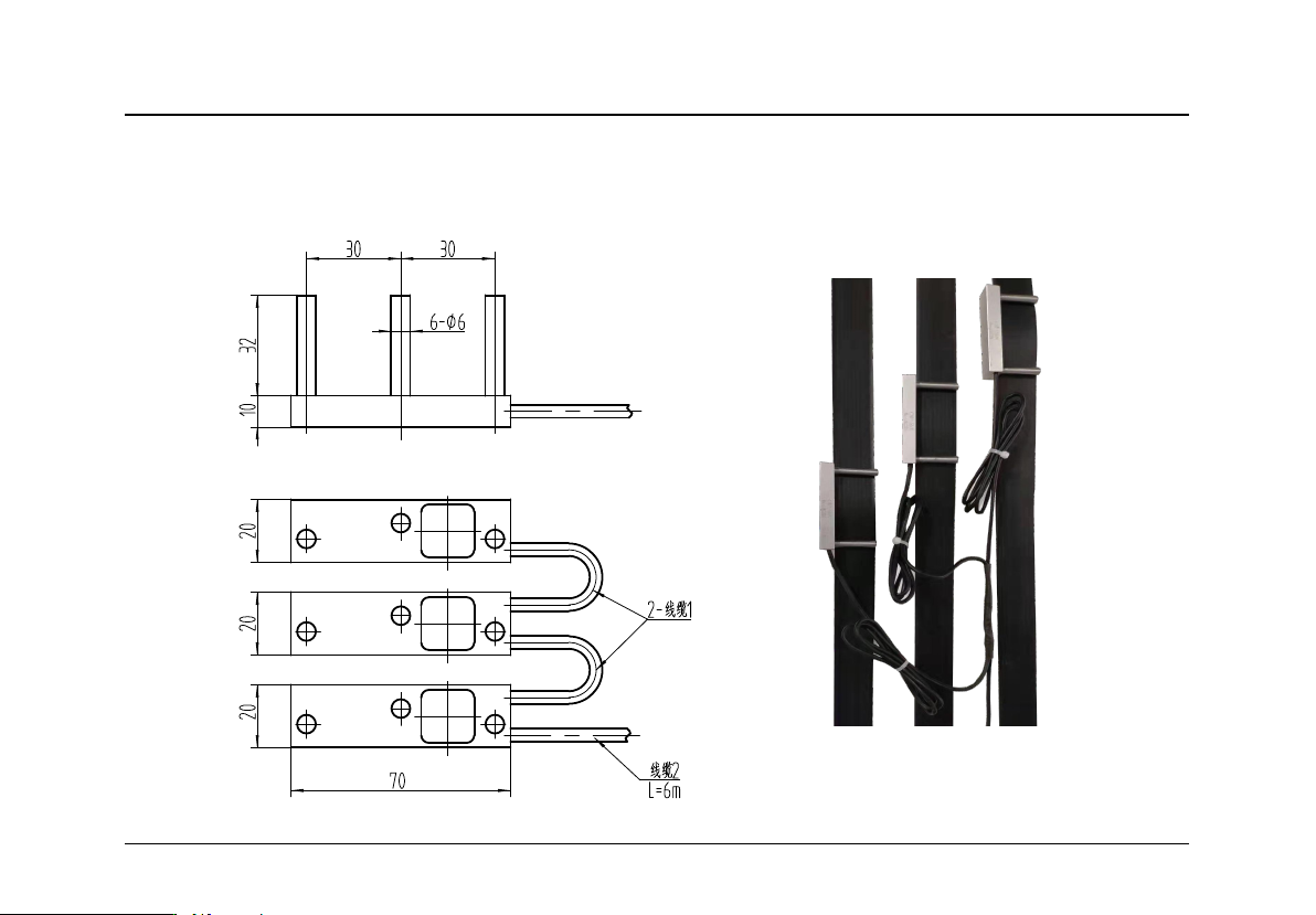
5. XCL-ZL/P2 type Intelligent loading Sensor size and installation method
5.1 Sensor size diagram (Measuring Range:5KN、8KN) 5.2 Installation Method
Technical File of EWD-RLG-SJ3 Serial Intelligent Elevator Weighing Device [User’s Guide]
Page
34
of 36
6. XCL-ZL/P3 type Intelligent loading Sensor size and installation method
6.1 Sensor size diagram (Measuring Range:5KN、8KN) 6.2 Installation Method
